4-The Network Layer_a router forwards a packet by examining the value -程序员宅基地
技术标签: github 网络 计算机网络:自顶向下方法-第6版
Please indicate the source: http://blog.csdn.net/gaoxiangnumber1
Welcome to my github: https://github.com/gaoxiangnumber1
4.1 Introduction
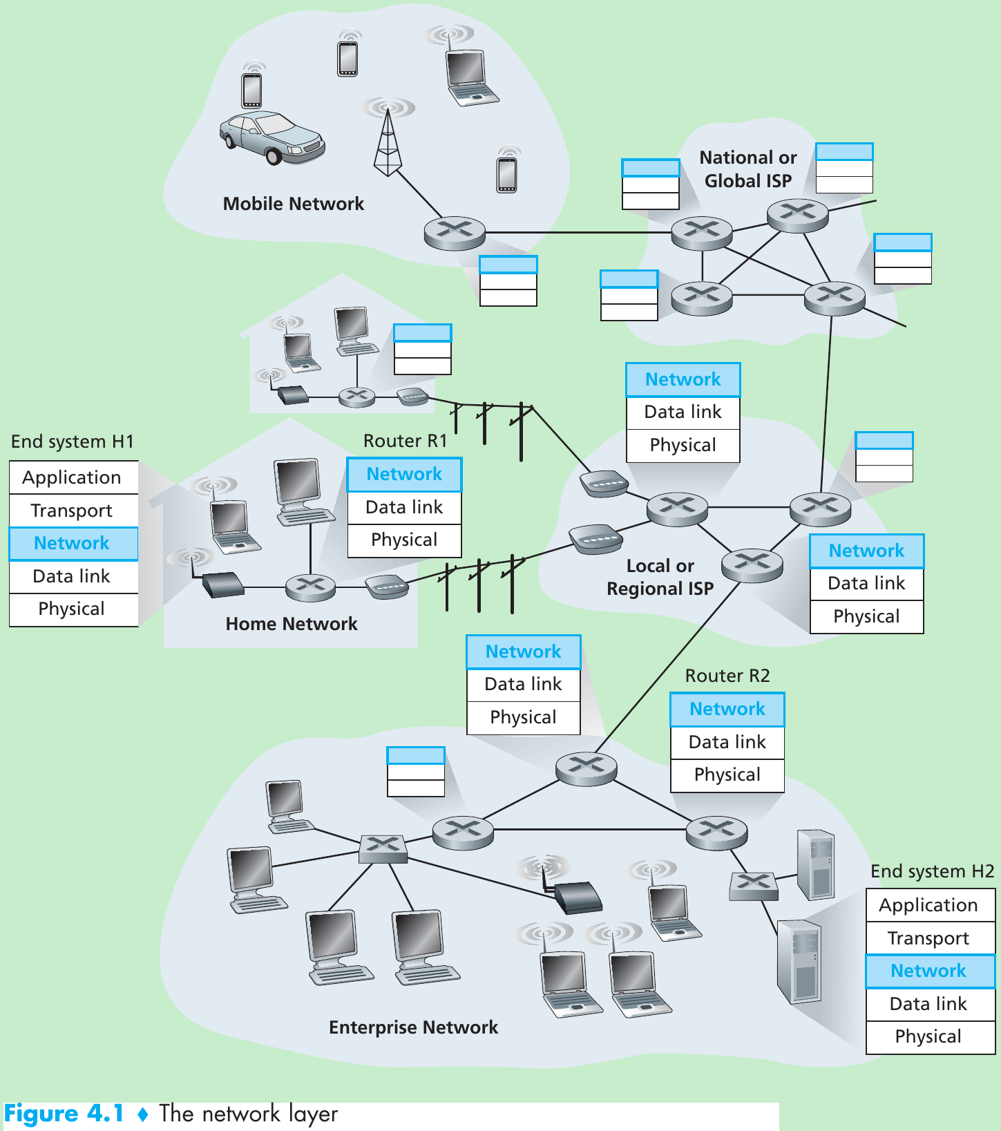
- Figure 4.1 shows a network with two hosts, H1 and H2, and several routers on the path between H1 and H2. Suppose H1 is sending information to H2.
- The network layer in H1 takes segments from the transport layer in H1, encapsulates each segment into a datagram(a network-layer packet), and then sends the datagrams to its nearby router, R1.
- At the receiving host, H2, the network layer receives the datagrams from its nearby router R2, extracts the transport-layer segments, and delivers the segments up to the transport layer at H2.
- The primary role of the routers is to forward datagrams from input links to output links. Except for control purposes, routers do not run application and transport-layer protocols.
4.1.1 Forwarding and Routing
- The role of the network layer is to move packets from a sending host to a receiving host. Two important network-layer functions can be identified:
- Forwarding refers to the router-local action of transferring a packet from an input link interface to the appropriate output link interface.
- Routing refers to the network-wide process that determines the end-to-end paths that packets take from source to destination. The algorithms that calculate these paths are referred to as routing algorithms.
- Every router has a forwarding table. A router forwards a packet by examining the value of a field in the arriving packet’s header, and then using this header value to index into the router’s forwarding table. The value stored in the forwarding table entry for that header indicates the router’s outgoing link interface to which that packet is to be forwarded.
- Depending on the network-layer protocol, the header value could be the destination address or an indication of the connection to which the packet belongs. Figure 4.2 provides an example.
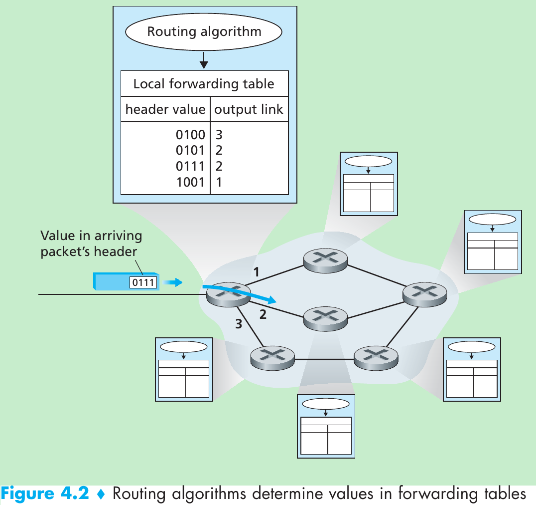
- The routing algorithm determines the values that are inserted into the routers’ forwarding tables. It may be centralized(e.g., with an algorithm executing on a central site and downloading routing information to each of the routers) or decentralized(i.e., with a piece of the distributed routing algorithm running in each router). In either case, a router receives routing protocol messages to configure its forwarding table.
- We use term “packet switch” to mean a general packet-switching device that transfers a packet from input link interface to output link interface, according to the value in a field in the header of the packet. Some packet switches that base their forwarding decision on values in the fields of the link layer frame are called link-layer switches(Chapter 5). Other packet switches that base their forwarding decision on the value in the network layer field are called routers. Routers are network-layer(layer 3) devices, but must also implement layer 2 protocols as well, since layer 3 devices require the services of layer 2 to implement their(layer 3) functionality.
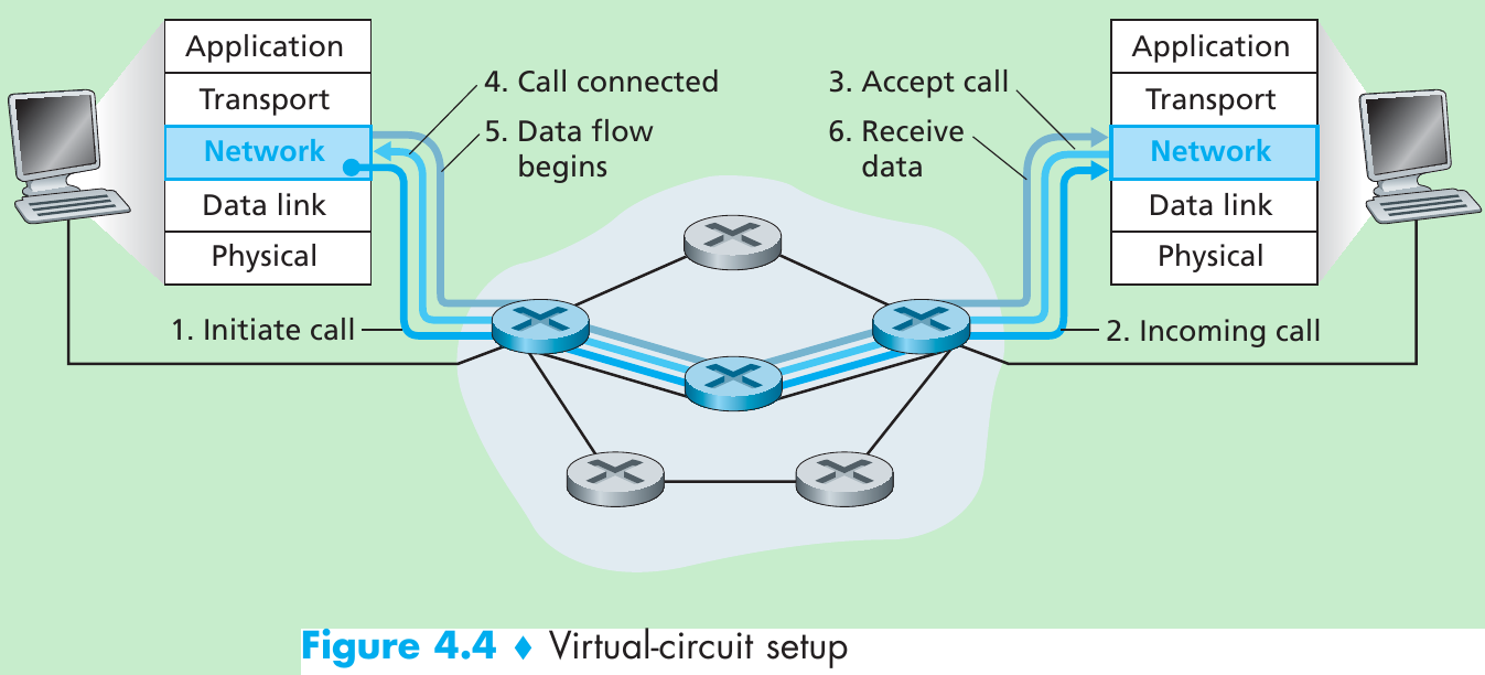
Connection Setup
- Except two functions(forwarding and routing), in some computer networks there is a third network-layer function, connection setup.
- Some network-layer architectures(ATM, frame relay, and MPLS) require the routers along the chosen path from source to destination to handshake with each other in order to set up state before network-layer data packets within a given source-to-destination connection can begin to flow. This process is called connection setup in the network layer.
4.1.2 Network Service Models
- The network service model defines the characteristics of end-to-end transport of packets between sending and receiving end systems.
- In the sending host, when the transport layer passes a packet to the network layer, specific services that could be provided by the network layer include:
• Guaranteed delivery: the packet will eventually arrive at its destination.
• Guaranteed delivery with bounded delay: guarantees delivery of the packet within a specified host-to-host delay bound(E.g., within 100 msec). - The following services could be provided to a flow of packets between a given source and destination:
• In-order packet delivery: packets arrive at the destination in the order that they were sent.
• Guaranteed minimal bandwidth: emulates the behavior of a transmission link of a specified bit rate(E.g., 1 Mbps) between sending and receiving hosts. As long as the sending host transmits bits at a rate below the specified bit rate, then no packet is lost and each packet arrives within a pre-specified host-to-host delay(E.g., within 40 msec).
• Guaranteed maximum jitter: the amount of time between the transmission of two successive packets at the sender is equal to the amount of time between their receipt at the destination(or this spacing changes by no more than some specified value).
• Security services: use a secret session key known only by a source and destination host, the network layer in the source host could encrypt the payloads of all datagrams being sent to the destination host. The network layer in the destination host would then be responsible for decrypting the payloads. - The Internet’s network layer only provides best-effort service. Table 4.1:

- The ATM network architecture provides for multiple service models, meaning that different connections can be provided with different classes of service within the same network.
- Two important ATM service models are constant bit rate and available bit rate service:
- Constant bit rate(CBR) ATM network service.
The goal of CBR service is to provide a flow of packets with a virtual pipe as if a dedicated fixed-bandwidth transmission link existed between sending and receiving hosts. So, a cell’s end-to-end delay, the variability in a cell’s end-to-end delay(jitter), and the fraction of cells that are lost or delivered late are all guaranteed to be less than specified values. These values are agreed upon by the sending host and the ATM network when the CBR connection is first established. - Available bit rate(ABR) ATM network service.
Cells may be lost under ABR service, but cannot be reordered, and a minimum cell transmission rate(MCR) is guaranteed to a connection using ABR service. If the network has enough free resources at a given time, a sender may be able to send cells successfully at a higher rate than the MCR. Section 3.6: ATM ABR service can provide feedback to the sender(in terms of a congestion notification bit, or an explicit rate at which to send) that controls how the sender adjusts its rate between the MCR and an allowable peak cell rate.
- Constant bit rate(CBR) ATM network service.
4.2 Virtual Circuit and Datagram Networks
- A network layer can provide connectionless service or connection service between two hosts. In all major computer network architectures, the network layer provides either connectionless or connection service, but not both. Providing only a connection service is called virtual-circuit(VC) networks; only a connectionless service is called datagram networks. Virtual-circuit and datagram networks are two fundamental classes of computer networks.
- Differences between network-layer connection/connectionless services and transport-layer connection/connectionless services:
- Network layer services are host-to-host services provided by the network layer for the transport layer; transport layer services are process-to-process services provided by the transport layer for the application layer.
- The implementations of connection service in the transport layer and in the network layer are different. The transport-layer connection-oriented service is implemented at the edge of the network in the end systems; the network-layer connection service is implemented in the routers in the network core as well as in the end systems.
4.2.1 Virtual-Circuit Networks
- Network-layer connections are called virtual circuits(VCs). A VC consists of
(1) a path(i.e., a series of links and routers) between the source and destination hosts,
(2) VC numbers, one number for each link along the path, and
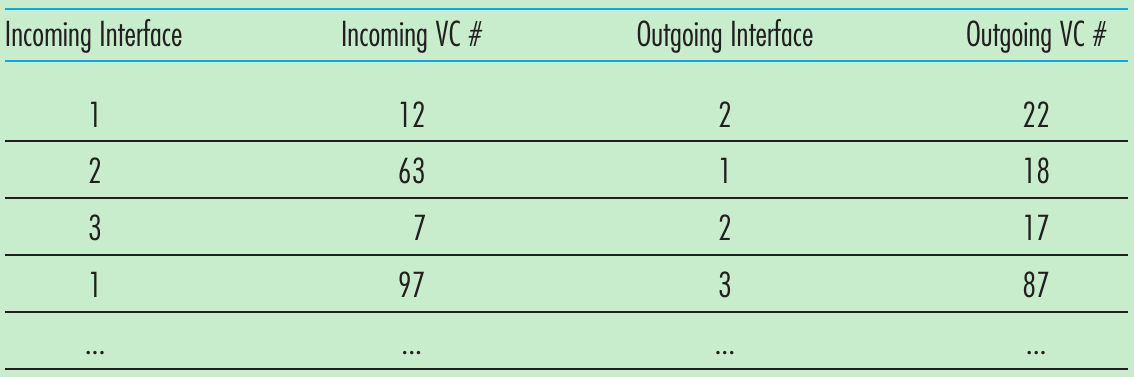
(3) entries in the forwarding table in each router along the path. - A packet belonging to a virtual circuit will carry a VC number in its header. Because a virtual circuit may have a different VC number on each link, each intervening router must replace the VC number of each traversing packet with a new VC number that is obtained from the forwarding table.
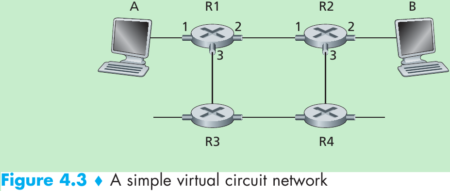
- Consider the network shown in Figure 4.3. The numbers next to the links of R1 in are the link interface numbers. Suppose that Host A requests that the network establish a VC between itself and Host B, also assume the network chooses the path A-R1-R2-B and assigns VC numbers 12, 22, and 32 to the three links in this path. When a packet leaves Host A, the value in the VC number field in the packet header is 12; when it leaves R1, the value is 22; and when it leaves R2, the value is 32.
- For a VC network, each router’s forwarding table includes VC number translation; the forwarding table in R1 might look like this:
- In a VC network, the network’s routers must maintain connection state information for the ongoing connections.
- Whenever a new connection is established across a router, a new connection entry must be added to the router’s forwarding table;
- Whenever a connection is released, an entry must be removed from the table.
- Why a packet doesn’t keep the same VC number on each of the links along its route?
- Replacing the number from link to link reduces the length of the VC field in the packet header.
- VC setup is simplified by permitting a different VC number at each link along the path. With multiple VC numbers, each link in the path can choose a VC number independently of the VC numbers chosen at other links along the path. If a common VC number were required for all links along the path, the routers would have to exchange and process a number of messages to agree on a common VC number to be used for a connection.
- Three phases in a virtual circuit:
- VC setup. The sending transport layer contacts the network layer, specifies the receiver’s address, and waits for the network to set up the VC. The network layer:
-1- Determine the series of links and routers through which all packets of the VC will travel between sender and receiver.
-2- Determine the VC number for each link along the path.
-3- Add an entry in the forwarding table in each router along the path.
-4- Reserve resources(bandwidth…) along the path of the VC. - Data transfer. Once the VC has been established, packets can begin to flow along the VC.
- VC teardown. This is initiated when the sender(or receiver) informs the network layer of its desire to terminate the VC. The network layer will then inform the end system on the other side of the network of the call termination and update the forwarding tables in each of the packet routers on the path to indicate that the VC no longer exists.
- VC setup. The sending transport layer contacts the network layer, specifies the receiver’s address, and waits for the network to set up the VC. The network layer:
- Distinction between VC setup at the network layer and connection setup at the transport layer(E.g., the TCP three-way handshake).
- Connection setup at the transport layer involves only the two end systems. During transport-layer connection setup, the two end systems alone determine the parameters(E.g., initial sequence number and flow-control window size) of their transport-layer connection. The routers within the network are completely oblivious to it.
- For a VC network layer, routers along the path between the two end systems are involved in VC setup, and each router is aware of all the VCs passing through it.
- The messages that the end systems send into the network to initiate or terminate a VC, and the messages passed between the routers to set up the VC(i.e., to modify connection state in router tables) are known as signaling messages, and the protocols used to exchange these messages are referred to as signaling protocols.
4.2.2 Datagram Networks
- In a datagram network, each time an end system wants to send a packet, it stamps the packet with the address of the destination end system and then pops the packet into the network. Figure 4-5.

- As a packet is transmitted from source to destination, it passes through a series of routers. Each of these routers has a forwarding table that maps destination addresses to link interfaces; when a packet arrives at the router, the router uses the packet’s destination address to look up the appropriate output link interface in the forwarding table. The router then intentionally forwards the packet to that output link interface.
- Suppose all destination addresses are 32 bits and our router has four links, numbered 0 through 3, and packets are to be forwarded to the link interfaces as follows:

- We could have the following forwarding table with just four entries:
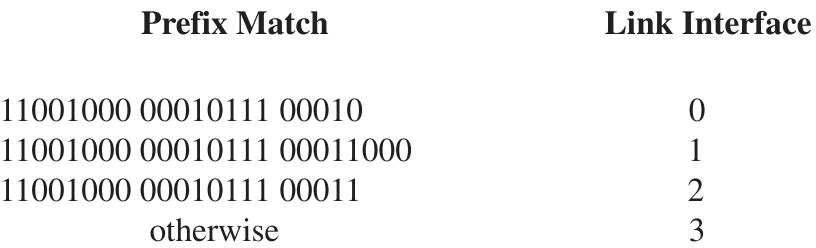
- The router matches a prefix of the packet’s destination address with the entries in the table; if there’s a match, the router forwards the packet to a link associated with the match. When there are multiple matches, the router finds the longest matching entry in the table and forwards the packet to the link interface associated with the longest prefix match.
- In a datagram network the forwarding tables are modified by the routing algorithms, which update a forwarding table every one-to-five minutes or so. In a VC network, a forwarding table in a router is modified whenever a new connection is set up through the router or whenever an existing connection through the router is torn down.
- Because forwarding tables in datagram networks can be modified at any time, a series of packets sent from one end system to another may follow different paths through the network and may arrive out of order.
4.2.3 Origins of VC and Datagram Networks
4.3 What’s Inside a Router?
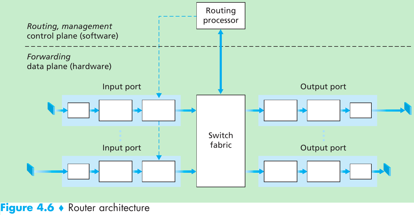
- A high-level view of a generic router architecture is shown in Figure 4.6. Four router components can be identified:
- Input ports. An input port performs several key functions.
-1- Perform the physical layer function of terminating an incoming physical link at a router(shown in the leftmost box of the input port and the rightmost box of the output port in Figure 4.6).
-2- Perform link-layer functions needed to interoperate with the link layer at the other side of the incoming link(shown in the middle boxes in the input and output ports).
-3- Perform the lookup function(shown in the rightmost box of the input port). It is here that the forwarding table is consulted to determine the router output port to which an arriving packet will be forwarded via the switching fabric.
Control packets are forwarded from an input port to the routing processor. - Switching fabric. The switching fabric connects the router’s input ports to its output ports and it is completely contained within the router.
- Output ports. An output port stores packets received from the switching fabric and transmits these packets on the outgoing link by performing the necessary link-layer and physical-layer functions. When a link is bidirectional, an output port will usually be paired with the input port for that link on the same line card(a printed circuit board containing one or more input ports, which is connected to the switching fabric).
- Routing processor. The routing processor executes the routing protocols(Section 4.6), maintains routing tables and attached link state information, and computes the forwarding table for the router. It also performs the network management functions(Chapter 9).
- Input ports. An input port performs several key functions.
- A router’s input ports, output ports, and switching fabric together implement the forwarding function and are almost implemented in hardware. These forwarding functions are sometimes collectively referred to as the router forwarding plane.
Why a hardware implementation is needed? Consider that with a 10 Gbps input link and a 64-byte IP datagram, the input port has only 51.2 ns to process the datagram before another datagram may arrive. If N ports are combined on a line card, the datagram-processing pipeline must operate N times faster: far too fast for software implementation. - While the forwarding plane operates at the nanosecond time scale, a router’s control functions(executing the routing protocols, responding to attached links that go up or down, and performing management functions) operate at the millisecond or second timescale. These router control plane functions are usually implemented in software and execute on the routing processor.
4.3.1 Input Processing
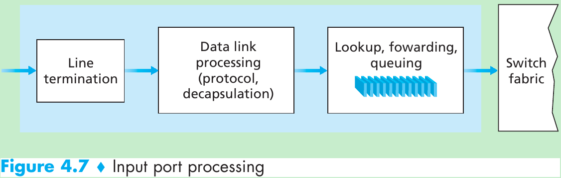
- A detailed view of input processing is given in Figure 4.7.
- The input port’s line termination function and link-layer processing implement the physical and link layers for that individual input link.
- The lookup action is that the router uses the forwarding table to look up the output port to which an arriving packet will be forwarded via the switching fabric. The forwarding table is computed and updated by the routing processor, with a shadow copy stored at each input port. The forwarding table is copied from the routing processor to the line cards over a separate bus(the dashed line from the routing processor to the input line cards in Figure 4.6). With a shadow copy, forwarding decisions can be made locally at each input port, without invoking the centralized routing processor on a per-packet basis and So avoiding a centralized processing bottleneck.
- Given the existence of a forwarding table, lookup is simple: we just search through the forwarding table looking for the longest prefix match. But at Gigabit transmission rates, this lookup must be performed in nanoseconds. So, techniques beyond a linear search through a large table are needed.
- Once a packet’s output port has been determined via the lookup, the packet can be sent into the switching fabric. In some designs, a packet may be temporarily blocked from entering the switching fabric if packets from other input ports are currently using the fabric. A blocked packet will be queued at the input port and then scheduled to cross the fabric at a later point in time.
- Beyond lookup action in input port processing, other actions must be taken:
(1) physical and link-layer processing must occur;
(2) the packet’s version number, checksum and time-to-live field(Section 4.4.1) must be checked and the latter two fields rewritten;
(3) counters used for network management(the number of IP datagrams received…) must be updated.
4.3.2 Switching
- The switching fabric is the heart of a router because packets are switched(i.e., forwarded) from an input port to an output port through this fabric. Switching can be accomplished in following ways(Figure 4.8).
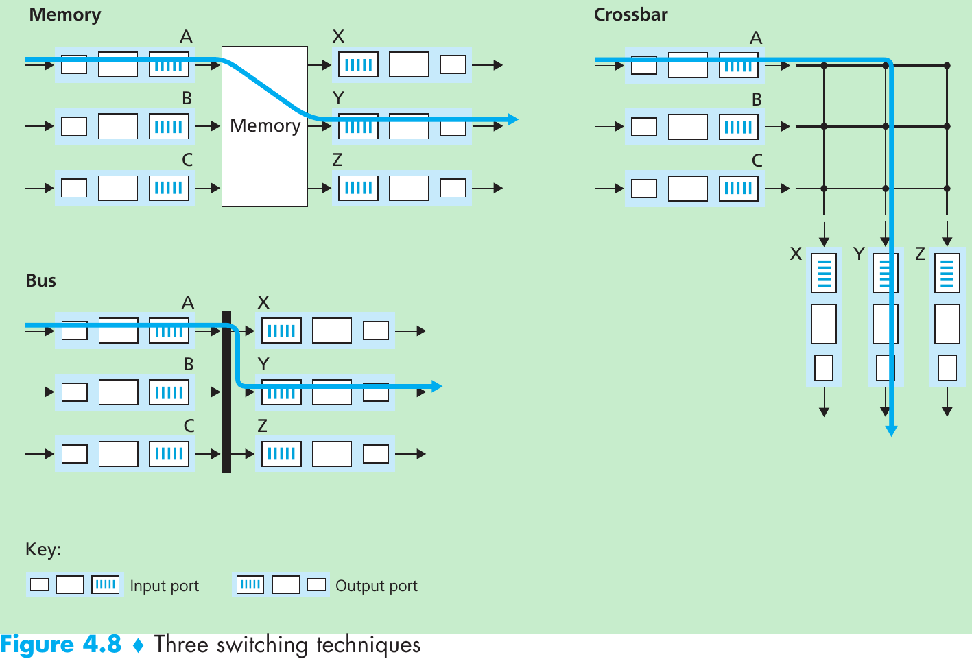
Switching via memory.
- The simplest, earliest routers were computers, with switching between input and output ports being done under direct control of the CPU(routing processor). Input and output ports functioned as I/O devices in operating system. An input port with an arriving packet first signaled the routing processor via an interrupt. The packet was then copied from the input port into processor memory. The routing processor then extracted the destination address from the header, looked up the appropriate output port in the forwarding table, and copied the packet to the output port’s buffers.
- If the memory bandwidth is B packets per second that can be written into, or read from memory, then the overall forwarding throughput(the total rate at which packets are transferred from input ports to output ports) must be less than B/2. Two packets cannot be forwarded at the same time, even if they have different destination ports, since only one memory read/write over the shared system bus can be done at a time.
- Many modern routers switch via memory. Difference from early routers is that the lookup of the destination address and the storing of the packet into the appropriate memory location are performed by processing on the input line cards. In some ways, routers that switch via memory are similar to shared-memory multiprocessors, with the processing on a line card switching(writing) packets into the memory of the appropriate output port.
Switching via a bus.
- An input port transfers a packet directly to the output port over a shared bus, without intervention by the routing processor. This is done by having the input port pre-pend a switch-internal label(header) to the packet indicating the local output port to which this packet is being transferred and transmitting the packet onto the bus. The packet is received by all output ports, but only the port that matches the label will keep the packet. The label is then removed at the output port, as this label is only used within the switch to cross the bus.
- If multiple packets arrive to the router at the same time, each at a different input port, all but one must wait since only one packet can cross the bus at a time. Because every packet must cross the single bus, the switching speed of the router is limited to the bus speed. Switching via a bus is often sufficient for routers that operate in small local area and enterprise networks.
Switching via an interconnection network.
- One way to overcome the bandwidth limitation of a single, shared bus is to use interconnection network.
- A crossbar switch is an interconnection network consisting of 2N buses that connect N input ports to N output ports(Figure 4.8). Each vertical bus intersects each horizontal bus at a crosspoint, which can be opened or closed at any time by the switch fabric controller that is part of the switching fabric itself. When a packet arrives from port A and needs to be forwarded to port Y, the switch controller closes the crosspoint at the intersection of buses A and Y, and port A then sends the packet onto its bus, which is picked up(only) by bus Y.
- Note that a packet from port B can be forwarded to port X at the same time, since A-to-Y and B-to-X packets use different input and output buses. So, crossbar networks are capable of forwarding multiple packets in parallel. But if two packets from two different input ports are destined to the same output port, then one will have to wait at the input, since only one packet can be sent over any given bus at a time.
- More sophisticated interconnection networks use multiple stages of switching elements to allow packets from different input ports to proceed towards the same output port at the same time through the switching fabric.
4.3.3 Output Processing
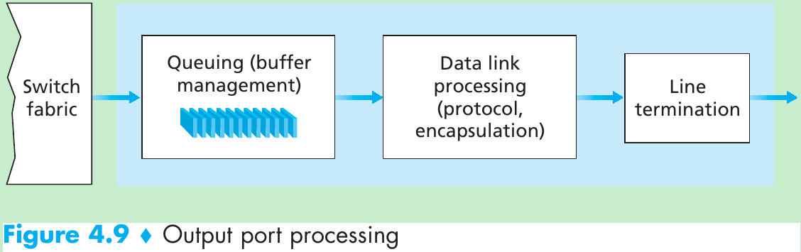
- Output port processing(Figure 4.9) takes packets that have been stored in the output port’s memory and transmits them over the output link. This includes selecting and de-queueing packets for transmission, and performing the needed link-layer and physical-layer transmission functions.
4.3.4 Where Does Queueing Occur?
- The location and extent of queueing(either at input port queues or output port queues) will depend on the traffic load, the relative speed of the switching fabric, and the line speed. As these queues grow large, the router’s memory can eventually be exhausted and packet loss will occur when no memory is available to store arriving packets. It is at these queues in router where packets are dropped and lost in the network.
- Suppose that the input and output line speeds(transmission rates) all have a transmission rate of R-line packets per second, and that there are N input ports and N output ports. Assume that all packets have the same fixed length, and the packets arrive to input ports in a synchronous manner(i.e., the time to send a packet on any link is equal to the time to receive a packet on any link and during such an interval of time, either
智能推荐
oracle 12c 集群安装后的检查_12c查看crs状态-程序员宅基地
文章浏览阅读1.6k次。安装配置gi、安装数据库软件、dbca建库见下:http://blog.csdn.net/kadwf123/article/details/784299611、检查集群节点及状态:[root@rac2 ~]# olsnodes -srac1 Activerac2 Activerac3 Activerac4 Active[root@rac2 ~]_12c查看crs状态
解决jupyter notebook无法找到虚拟环境的问题_jupyter没有pytorch环境-程序员宅基地
文章浏览阅读1.3w次,点赞45次,收藏99次。我个人用的是anaconda3的一个python集成环境,自带jupyter notebook,但在我打开jupyter notebook界面后,却找不到对应的虚拟环境,原来是jupyter notebook只是通用于下载anaconda时自带的环境,其他环境要想使用必须手动下载一些库:1.首先进入到自己创建的虚拟环境(pytorch是虚拟环境的名字)activate pytorch2.在该环境下下载这个库conda install ipykernelconda install nb__jupyter没有pytorch环境
国内安装scoop的保姆教程_scoop-cn-程序员宅基地
文章浏览阅读5.2k次,点赞19次,收藏28次。选择scoop纯属意外,也是无奈,因为电脑用户被锁了管理员权限,所有exe安装程序都无法安装,只可以用绿色软件,最后被我发现scoop,省去了到处下载XXX绿色版的烦恼,当然scoop里需要管理员权限的软件也跟我无缘了(譬如everything)。推荐添加dorado这个bucket镜像,里面很多中文软件,但是部分国外的软件下载地址在github,可能无法下载。以上两个是官方bucket的国内镜像,所有软件建议优先从这里下载。上面可以看到很多bucket以及软件数。如果官网登陆不了可以试一下以下方式。_scoop-cn
Element ui colorpicker在Vue中的使用_vue el-color-picker-程序员宅基地
文章浏览阅读4.5k次,点赞2次,收藏3次。首先要有一个color-picker组件 <el-color-picker v-model="headcolor"></el-color-picker>在data里面data() { return {headcolor: ’ #278add ’ //这里可以选择一个默认的颜色} }然后在你想要改变颜色的地方用v-bind绑定就好了,例如:这里的:sty..._vue el-color-picker
迅为iTOP-4412精英版之烧写内核移植后的镜像_exynos 4412 刷机-程序员宅基地
文章浏览阅读640次。基于芯片日益增长的问题,所以内核开发者们引入了新的方法,就是在内核中只保留函数,而数据则不包含,由用户(应用程序员)自己把数据按照规定的格式编写,并放在约定的地方,为了不占用过多的内存,还要求数据以根精简的方式编写。boot启动时,传参给内核,告诉内核设备树文件和kernel的位置,内核启动时根据地址去找到设备树文件,再利用专用的编译器去反编译dtb文件,将dtb还原成数据结构,以供驱动的函数去调用。firmware是三星的一个固件的设备信息,因为找不到固件,所以内核启动不成功。_exynos 4412 刷机
Linux系统配置jdk_linux配置jdk-程序员宅基地
文章浏览阅读2w次,点赞24次,收藏42次。Linux系统配置jdkLinux学习教程,Linux入门教程(超详细)_linux配置jdk
随便推点
matlab(4):特殊符号的输入_matlab微米怎么输入-程序员宅基地
文章浏览阅读3.3k次,点赞5次,收藏19次。xlabel('\delta');ylabel('AUC');具体符号的对照表参照下图:_matlab微米怎么输入
C语言程序设计-文件(打开与关闭、顺序、二进制读写)-程序员宅基地
文章浏览阅读119次。顺序读写指的是按照文件中数据的顺序进行读取或写入。对于文本文件,可以使用fgets、fputs、fscanf、fprintf等函数进行顺序读写。在C语言中,对文件的操作通常涉及文件的打开、读写以及关闭。文件的打开使用fopen函数,而关闭则使用fclose函数。在C语言中,可以使用fread和fwrite函数进行二进制读写。 Biaoge 于2024-03-09 23:51发布 阅读量:7 ️文章类型:【 C语言程序设计 】在C语言中,用于打开文件的函数是____,用于关闭文件的函数是____。
Touchdesigner自学笔记之三_touchdesigner怎么让一个模型跟着鼠标移动-程序员宅基地
文章浏览阅读3.4k次,点赞2次,收藏13次。跟随鼠标移动的粒子以grid(SOP)为partical(SOP)的资源模板,调整后连接【Geo组合+point spirit(MAT)】,在连接【feedback组合】适当调整。影响粒子动态的节点【metaball(SOP)+force(SOP)】添加mouse in(CHOP)鼠标位置到metaball的坐标,实现鼠标影响。..._touchdesigner怎么让一个模型跟着鼠标移动
【附源码】基于java的校园停车场管理系统的设计与实现61m0e9计算机毕设SSM_基于java技术的停车场管理系统实现与设计-程序员宅基地
文章浏览阅读178次。项目运行环境配置:Jdk1.8 + Tomcat7.0 + Mysql + HBuilderX(Webstorm也行)+ Eclispe(IntelliJ IDEA,Eclispe,MyEclispe,Sts都支持)。项目技术:Springboot + mybatis + Maven +mysql5.7或8.0+html+css+js等等组成,B/S模式 + Maven管理等等。环境需要1.运行环境:最好是java jdk 1.8,我们在这个平台上运行的。其他版本理论上也可以。_基于java技术的停车场管理系统实现与设计
Android系统播放器MediaPlayer源码分析_android多媒体播放源码分析 时序图-程序员宅基地
文章浏览阅读3.5k次。前言对于MediaPlayer播放器的源码分析内容相对来说比较多,会从Java-&amp;gt;Jni-&amp;gt;C/C++慢慢分析,后面会慢慢更新。另外,博客只作为自己学习记录的一种方式,对于其他的不过多的评论。MediaPlayerDemopublic class MainActivity extends AppCompatActivity implements SurfaceHolder.Cal..._android多媒体播放源码分析 时序图
java 数据结构与算法 ——快速排序法-程序员宅基地
文章浏览阅读2.4k次,点赞41次,收藏13次。java 数据结构与算法 ——快速排序法_快速排序法